¶ Cutting Tool Fundamentals
¶ Rotation Direction
All tools (except left-handed taps) rotate clockwise (M3) when viewed from the machine spindle looking down at the part.
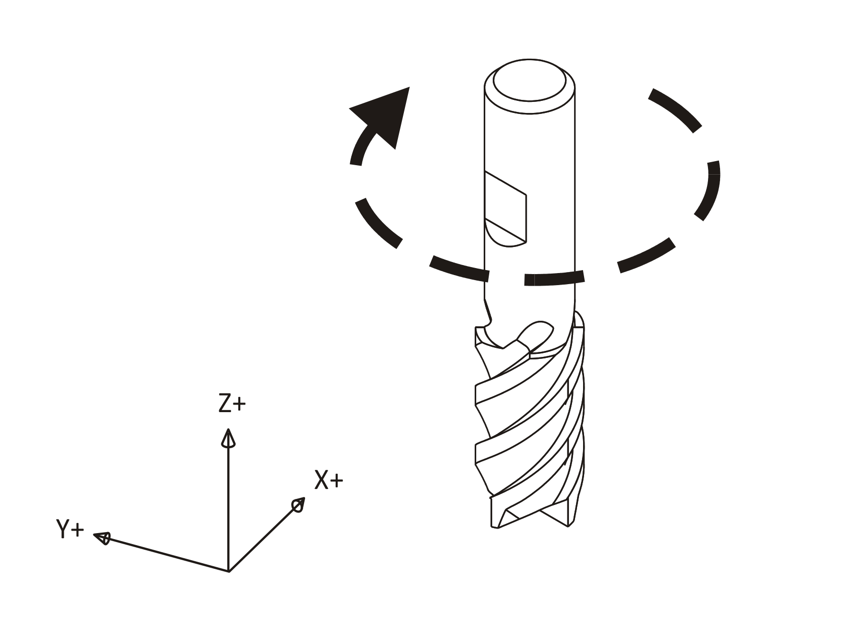
Clockwise Tool Rotation
¶ Chip Formation
Cutting tools remove metal by shearing action as illustrated in Figure 11 below. As the tool advances into the material it causes a small amount of the material to shear away, forming a chip.
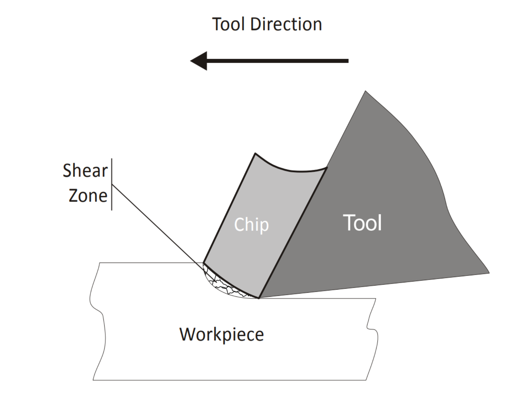
Chip Formation Diagram
¶ Chip Load
The thickness of material sheared away by each cutting tooth is called the feed per tooth, or chip load. As the chip is ejected from the work area it carries with it some of the heat generated by the shearing process.
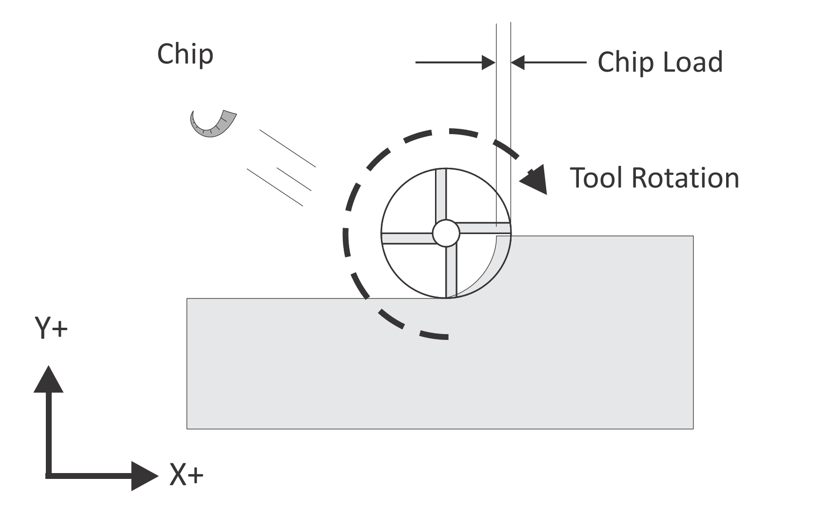
Chip Load
A methodology for calculating cutting speeds and feeds is presented later in this chapter. One of the best ways to validate cutting speeds and feeds is to observe the chips created by the machining process. Chips should be curled and may change color due to heating. After gaining some experience machinists are able to adjust cutting speeds and feeds based in part on the size, shape, and color of chips and on the sound produced by the cutting process
¶ Climb vs. Conventional Milling
Milling tools can advance through the material so that the cutting flutes engage the material at maximum thickness and then decreases to zero. This is called Climb Milling. Cutting in the opposite direction causes the tool to scoop up the material, starting at zero thickness and increasing to maximum. This is called Conventional Milling. Conventional milling is used often on manual machines because backlash in the machine lead screws causes the tool to lurch when climb cutting. This is not a problem on CNC machines because they use ball screws. Conventional milling causes the tool to rub against the cutting surface, work hardening the material, generating heat, and increasing tool wear. Raking chips across the finished surface also produces a poorer surface finish. Unless specifically recommended by the tool manufacturer for the material being milled, always use climb milling on a CNC. Climb milling produces far less cutting pressure and heat, leaves a better surface finish, and results in longer tool life.
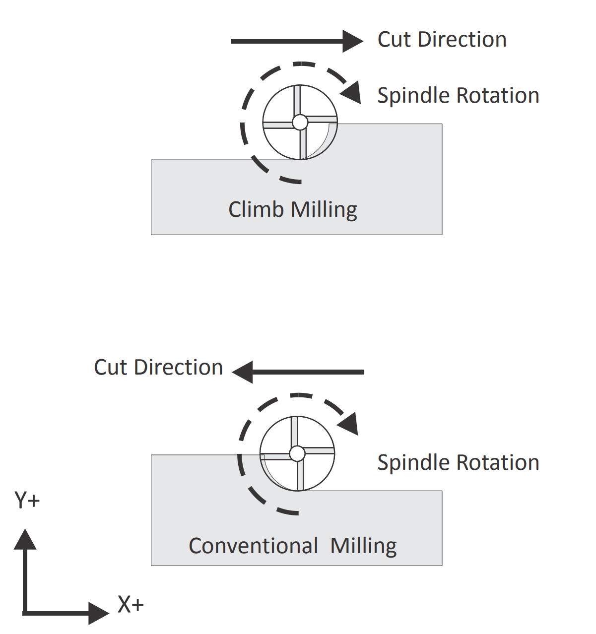
Climb vs. Conventional Milling
¶ Cutting Speeds and Feeds Formulas
The tool moves through the material at a specified rotational speed, defined in revolutions per minute (RPM), and feed rate, defined in inches per minute (IPM). Probably the most vexing problem for the beginning CNC machinist is selecting proper cutting speeds and feeds. This selection is actually more difficult on a CNC than a manual mill because, with a manual mill, the operator can feel the cutting pressure and alter the feed based in part on the cutting force.
CNC mills require calculating speeds and feeds in advance. These speeds and feeds can, and often are, adjusted at the machine based on chip shape and color, cutting sound, and machine horsepower meter readings.
The best source of data about cutting speeds and feeds for a specific tool, application, and material is the tool supplier. Much of this data is found on manufacturer’s web sites or printed tooling catalogs. Tool sales representatives can be a valuable resource, so if you do a lot of machining, develop a good relationship with a knowledgeable representative.
Another source of speeds and feeds data is CAD/CAM software. These have become increasingly sophisticated and often provide good cutting data.
Yet even the best speed and feed data is just a starting point. Speeds and feeds require adjustment due to many factors including the maximum spindle speed or horsepower of the machine, rigidity of work holding, and the quality and condition of the machine tool itself. The following pages provide cutting data for the most commonly machined materials and a methodology for calculating speeds and feeds. As always, use common sense. If the part is held by double sided tape, feeds based on vise work holding are probably too high. If the tool is very long and thin, speeds and feeds will likely require reduction.
¶ Speed Formula
Milling machine cutting speeds are derived from the following formula:
is the rotational frequency of the tool (Spindle Speed) in revolutions per minute (RPM).
(Surface Feet per Minute) is the speed at which the material moves past the cutting edge (outside diameter) of the tool in feet per minute. SFM values depend on the tool type, tool material, and material being machined.
is the circumference of the cutting tool in feet.
¶ How Speed Formula is Derived
Because cutting tools are defined by their diameter in inches, this formula is rewritten and simplified as follows:
is the tool diameter in inches.
is a constant derived from 12/𝜋 which converts the tool circumference in feet to diameter in inches.
¶ Feed Formula
Cutting feeds are in (IPM) and use the following formula:
is the linear feed of the tool through the material in inches per minute.
is the result of the speed formula (Figure 15) in revolutions per minute.
is the chip load, or how much material each cutting edge of the tool removes per revolution. Chip load is sometimes referred to as feed per tooth (FPT) or inches per rev (IPR).
is the number of cutting flutes. (For a twist drill, this value is one.)
¶ Tap Feed Formula
For tapping operations, feed rate is based on the number of threads per inch and feed rate:
is the linear feed of the tool through the material in inches per minute.
is the result of the previous formula in revolutions per minute.
the threads per inch of the tap. For example, the TPI of a ¼-‐20 tap is 20.
¶ Speed/Feed Example
¶ Milling Speed/Feed Example
Problem: Calculate the cutting speed and feed for a milling operation given the following values:
| Parameter | Value |
|---|---|
| Tool | .500in |
| NumFlutes | 4 |
| SFM | 600ft/min |
| IPR | .005in |
Solution
Step 1: Calculate RPM
Step 2: Calculate IPM
Note: Round off milling speeds and feeds to the nearest integer.
¶ Drill Speed/Feed Example
Problem: Calculate the cutting speed and feed for a drill operation given the following values:
| Parameter | Value |
|---|---|
| Tool Diameter | .201in |
| SFM | 250ft/min |
| IPR | .002in |
Solution:
Step 1: Caculate RPM
Step 2: Calculate IPM
Note: Round off drilling feeds to the first decimal point.
¶ Tap Speed/Feed Example
Problem: Calculate the cutting speed and feed for a ¼-‐24 tap operation given the following values:
| Parameter | Value |
|---|---|
| Tool Diameter | .25in |
| SFM | 100ft/min |
| IPR | 24 |
Solution:
Step 1: Caculate RPM
Step 2: Calculate IPM
Note: Round off tapping feeds to three decimal points or the maximum number the machine allows.
¶ Maximum Spindle Speed Example
In cases where the calculated spindle speed exceeds the machine capabilities, program the maximum spindle speed of the machine and use this value in the feed calculation.
Problem: Calculate the cutting speed and feed for a milling operation given the following values:
| Parameter | Value |
|---|---|
| Tool Diameter | .125in |
| NumFlutes | 2 |
| SFM | 300ft/min |
| IPR | .003in/rev |
| Maximum RPM | 7,500rev/min |
Solution:
Step 1: Caculate RPM
Step 2: Calculate IPM
¶ Cutting Data
Tables on the following pages provide basic speed, feed and cutting data for some of the materials commonly used for prototypes. Use the tool manufacturer’s data instead whenever it is available.
¶ Mill Cutting Speed
SFM surface mm/min
| Material | HSS | Carbide |
|---|---|---|
| Aluminum | 180 | 240 |
| Brass | 50 | 50 |
| Delrin | 120 | 240 |
| Polycarbonate | 90 | 150 |
| Stainless Steel (303) | 25 | 100 |
| Steel (4140) | 20 | 100 |
SFM surface ft/min
| Material | HSS | Carbide |
|---|---|---|
| Aluminum | 600 | 800 |
| Brass | 175 | 175 |
| Delrin | 400 | 800 |
| Polycarbonate | 300 | 500 |
| Stainless Steel (303) | 80 | 300 |
| Steel (4140) | 70 | 350 |
¶ Drill Cutting Speeds (SFM)
surface ft/min
| Material | Drilling | C-Sink | Reamer | Tap |
|---|---|---|---|---|
| Aluminum | 300 | 200 | 150 | 100 |
| Brass | 120 | 90 | 66 | 100 |
| Delrin | 150 | 100 | 75 | 100 |
| Polycarbonate | 240 | 160 | 120 | 100 |
| Stainless Steel (303) | 50 | 35 | 25 | 35 |
| Steel (4140) | 90 | 60 | 45 | 35 |
Tip: Never use tools that have been used to machine metal to cut plastic. The sharp edge of the tool will be compromised and cutting performance and finish will suffer. A good practice is to keep two sets of tools: one for plastic and one for metal.
Tip: High speed steel cutters work best for plastics. Carbide cutters work better for aluminum and other metals.
Cutting Feed (IPR) in/rev
| Material | Tool Diameter Range (in) | ||||
|---|---|---|---|---|---|
| Milling | |||||
| Aluminum | .002 | .002 | .005 | .006 | .007 |
| Brass | .001 | .002 | .002 | .004 | .005 |
| Delrin | .002 | .002 | .005 | .006 | .007 |
| Polycarbonate | .001 | .003 | .006 | .008 | .009 |
| Stainless Steel (303) | .0005 | .001 | .002 | .003 | .004 |
| Steel (4140) | .0005 | .0005 | .001 | .002 | .003 |
| Drilling | .002 | .004 | .005 | .010 | .015 |
| Reaming | .005 | .007 | .009 | .012 | .015 |
¶ Best Practice Machining Parameters
Best practice machining parameters for prototype and short-production milling are different than for mass production. Production machining is obsessed with minimizing run time and maximizing tool life because even small improvements per part can result in significant cost savings. Prototype and short run production seeks to maximize reliability. Obviously, it does not make sense to risk breaking a tool or scrapping a part trying to save a few seconds if only making a few parts. Tables 8 and 9 on the following pages list recommended machining parameters for prototypes. The values are relatively conservative and work well for materials and tool types listed on the previous pages. For materials or tools not listed, consult cutting data from the tool manufacturer.
Recommended Machining Parameters
| Operation | Parameter | Value |
|---|---|---|
| All | Clearance Height | 1.0 inches |
| All | Rapid Height | As need to clear clamps and fixtures |
| Mill (Roughing) | Stepover (XY) | 50-80% of tool dia. |
| Mill (Roughing) | Stepover (Z) | 25-50% of tool dia. |
| Dill | Peck Increment | .05 inches |
| Stop Drill | Dwell | .5 seconds |
Stock Finish Allowance
| Operation | Tool Diameter Range (in) | ||||
|---|---|---|---|---|---|
| <.125 | .125-.25 | .25-.5 | .5-.1 | >1. | |
| Milling (XY) | .001 | .005 | .015 | .020 | .020 |
| Milling (Z) | .001 | .002 | .005 | .005 | .005 |
| Reaming | .005 | .010 | .012 | .020 | .030 |
¶ Troubleshooting Speed/Feed Problems
Do not make the mistake of thinking that the only option when encountering a machining problem is to reduce feed rate. Sometimes that is the worst thing to do and decreasing speed and increasing feed may be a better option. Be methodical. When a problem occurs, stop. Analyze what is happening, draw on all available resources, and then devise a solution to correct the problem. The Machinery’s Handbook (Industrial Press Inc, 2008, New York, NY, ISBN: 978‐8311‐2800‐5) contains extensive information about diagnosing and correcting cutting tool problems. This book is an essential reference for anyone using machine tools.