¶ Overview

CNC Milling (image credit: Greg Rosenke)
Machining is a process of removing material from a workpiece to create a desired shape. The workpiece is typically a piece of raw material, such as metal, plastic, or wood. The process is performed using a variety of tools, such as lathes, milling machines, and grinders. The workpiece is held in place by a fixture, and the cutting tool is moved across the workpiece to remove material. The cutting tool is typically a drill bit, end mill, or lathe tool. The process is controlled by a computer, which is programmed to move the cutting tool in a specific pattern to create the desired shape. This process is known as computer numerical control (CNC) machining.
¶ Terminology
- Workpiece: The raw material that is being machined.
- Fixture: Everything that holds the workpiece in place during machining, such as a vise or chuck.
- Cutting Tool: The tool that removes material from the workpiece, such as a drill bit or end mill.
- Spindle: The rotating shaft that holds the cutting tool.
¶ Turning vs. Milling
Machining can be divided into two main categories: turning and milling. Turning is the process of removing material from a workpiece by rotating it against a cutting tool. Milling is the process of removing material from a workpiece by moving a cutting tool across it. Turning is typically used to create cylindrical shapes, such as shafts and bushings, while milling is used to create flat surfaces and complex shapes.
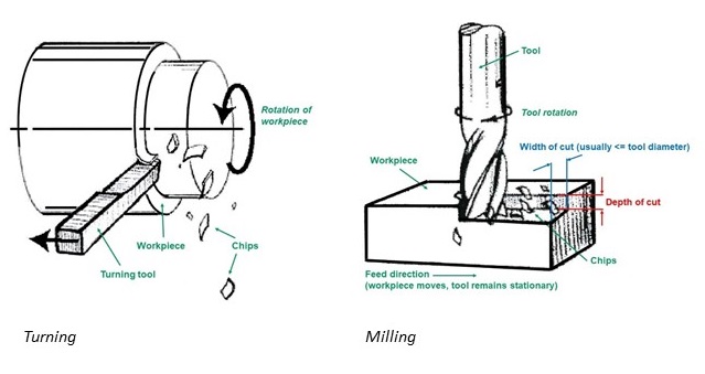
Turning and Milling (image credit: https://www.aldermantooling.co.uk/)
¶ 3-Axis, 4-Axis, and 5-Axis Machining
Milling machines can be classified based on the number of axes they can move along. A 3-axis machine can move the cutting tool along the X, Y, and Z axes. A 4-axis machine can also rotate the workpiece around the A axis. A 5-axis machine can rotate the workpiece around the B axis as well.
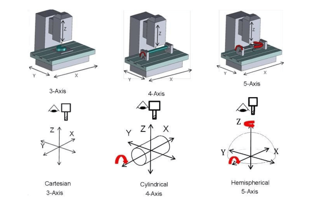
3-Axis, 4-Axis, and 5-Axis Machining (image credit: https://blog.goldsupplier.com/)
With more axes of movement, a machine can create more complex shapes and reduce the number of setups required to machine a part. However, more axes also increase the complexity of the machine and the programming required to operate it.
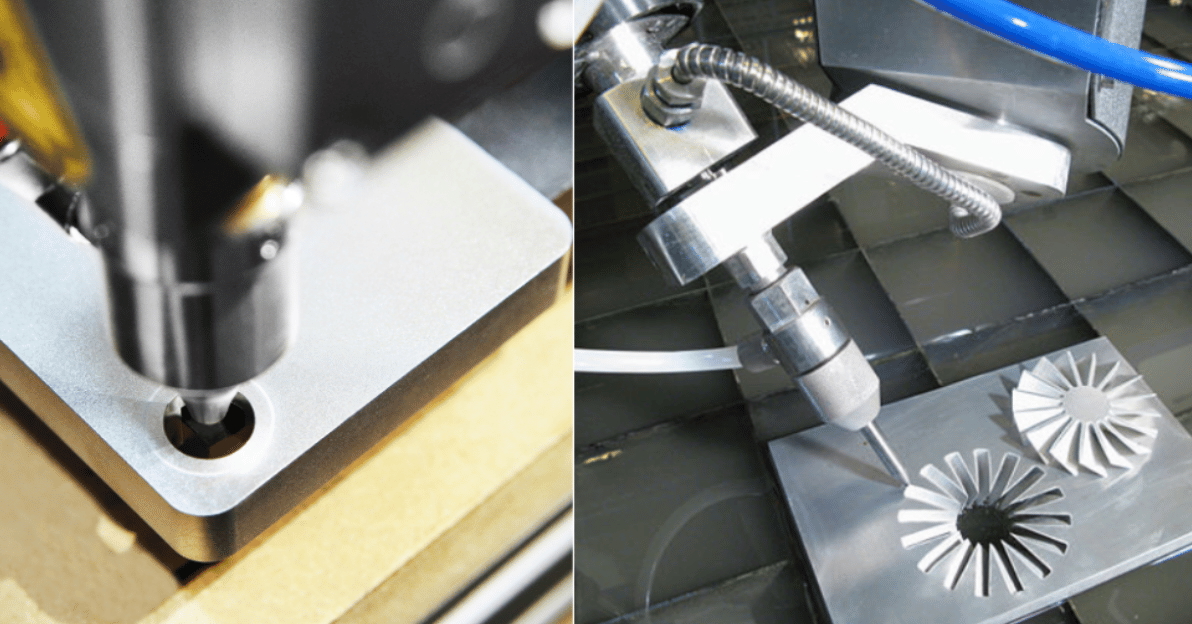
3-Axis vs 5-Axis Machining, machine on the right is a 5 axis water jet (image credit: https://blog.goldsupplier.com/)
¶ Workflow
The general workflow to go produce a part using CNC machining is as follows:
- Design the part with how it will be machined in mind.
- Set up machines, tools, fixtures, and coordinate systems.
- Set up processes, including tools, cutting parameters, and tool path parameters.
- Generate path, simulate, and verify the tool path.
- Post-process the tool path to generate machine code.
- Prepare the machines, materials, and tools.
- Load the machine code and execute the program to produce the part.
¶ Processes
The processes used in CNC machining are determined by the geometry of the part, the material being machined, and the desired finish. Common processes include:
- Drill
- Rough
- Finish
- Contour
You typically follow a sequence of processes to produce a part, to optimize the machining time and safety.
For example, you may first drill holes, then rough out the part, and finish the part to achieve the desired surface finish and dimensional accuracy, then finally machine the contours.
Image used in this section is from the University of Michigan's Fab lab.
¶ Drill
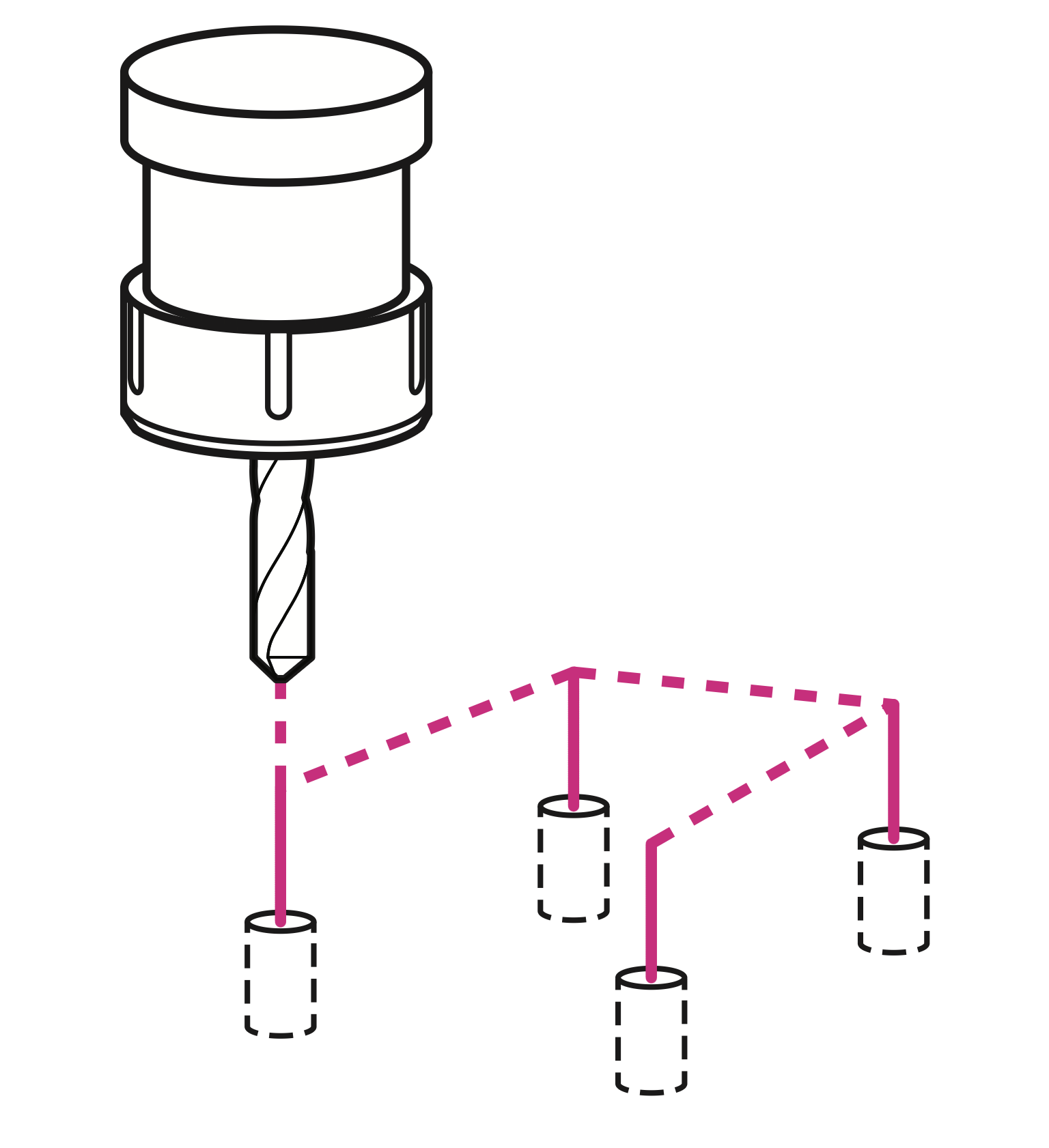
Uses a drill bit to remove material by plunging vertically into the stock.
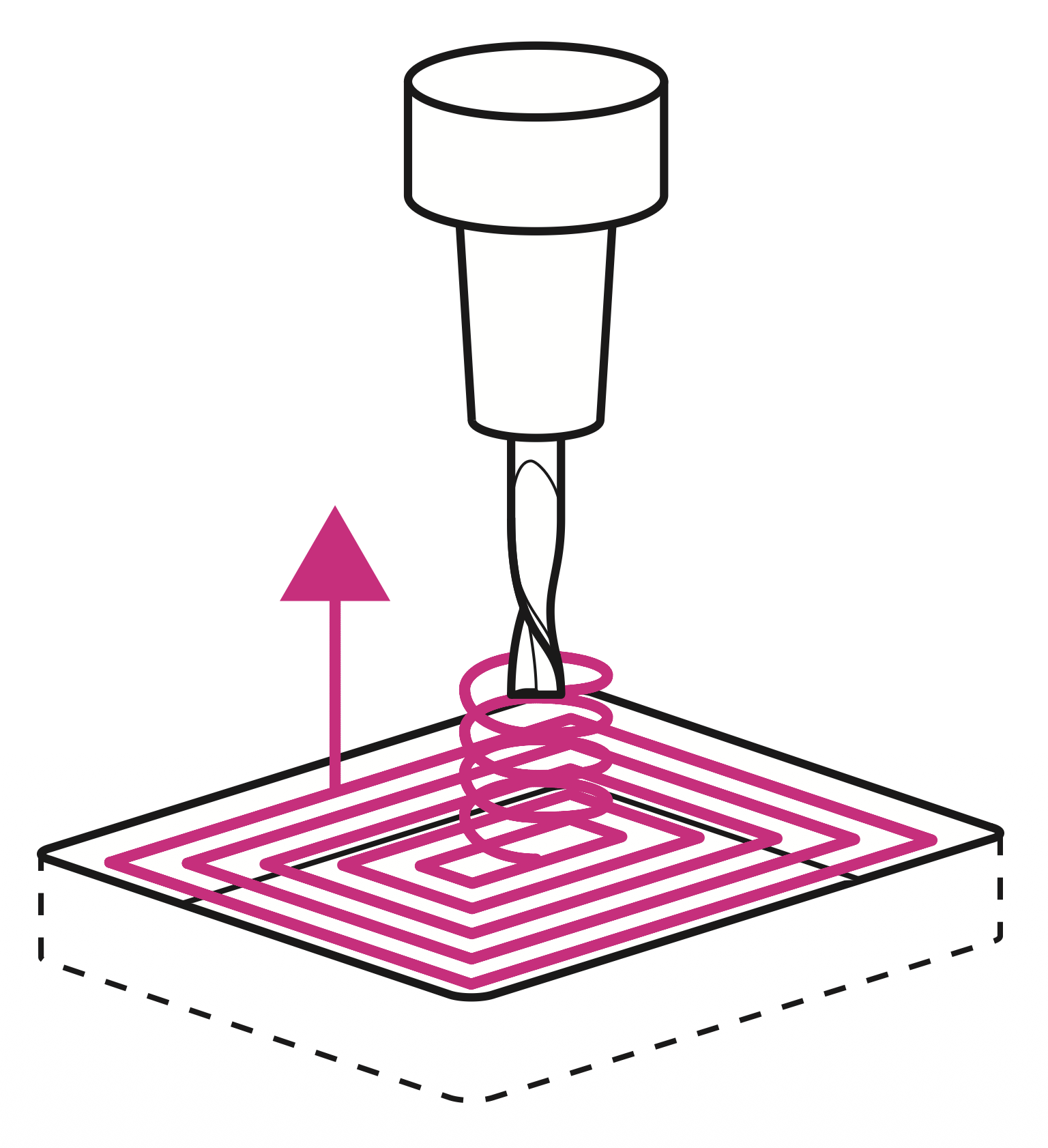
Removes material from a defined area to create a cavity or pocket. The tool moves in a pattern that covers the entire area of the pocket, typically using a zig-zag or spiral tool path.
¶ Rough
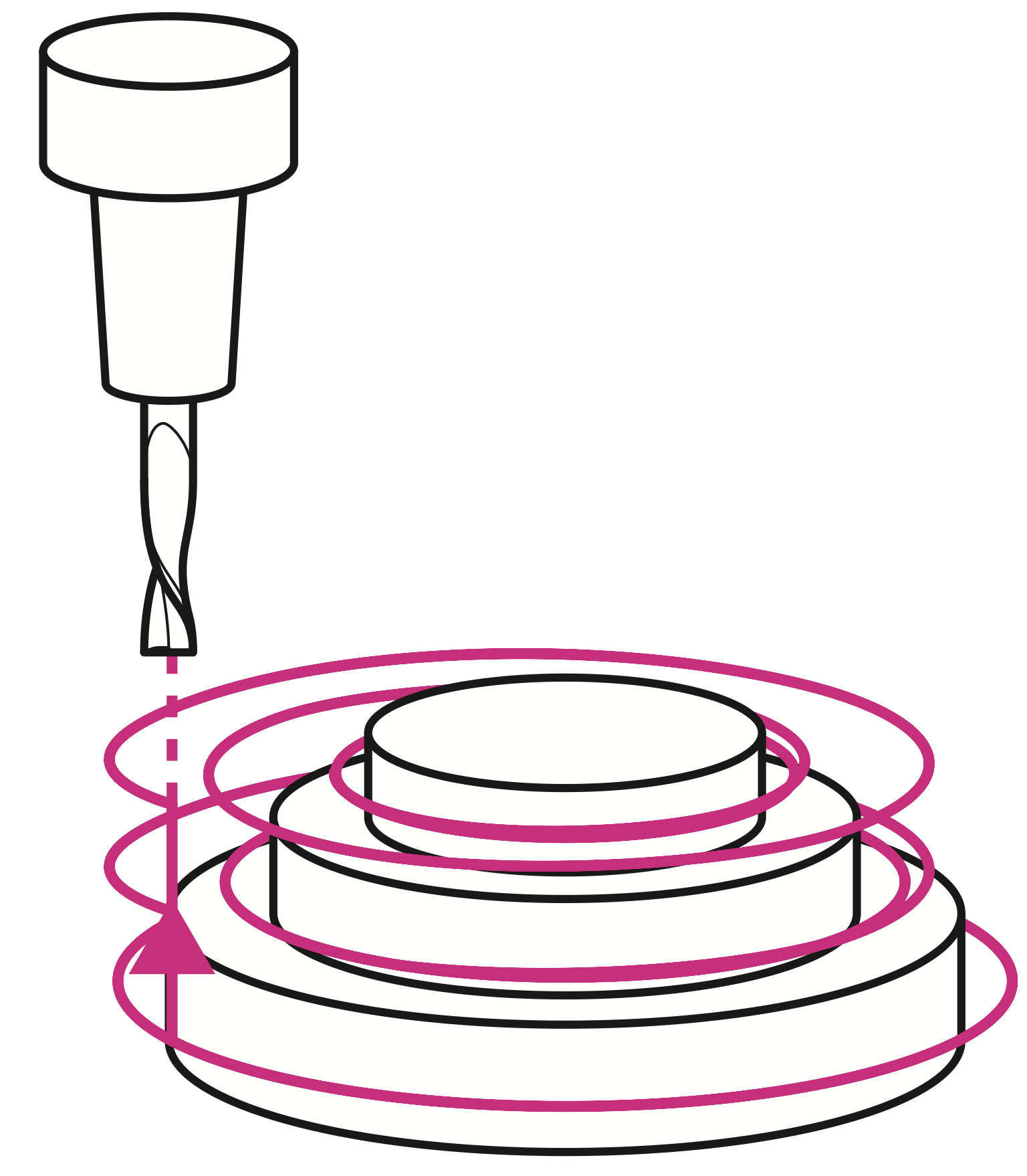
Removes large amounts of material quickly to create a rough shape of the part. The tool path is designed to maximize material removal while minimizing tool wear.
¶ Finish
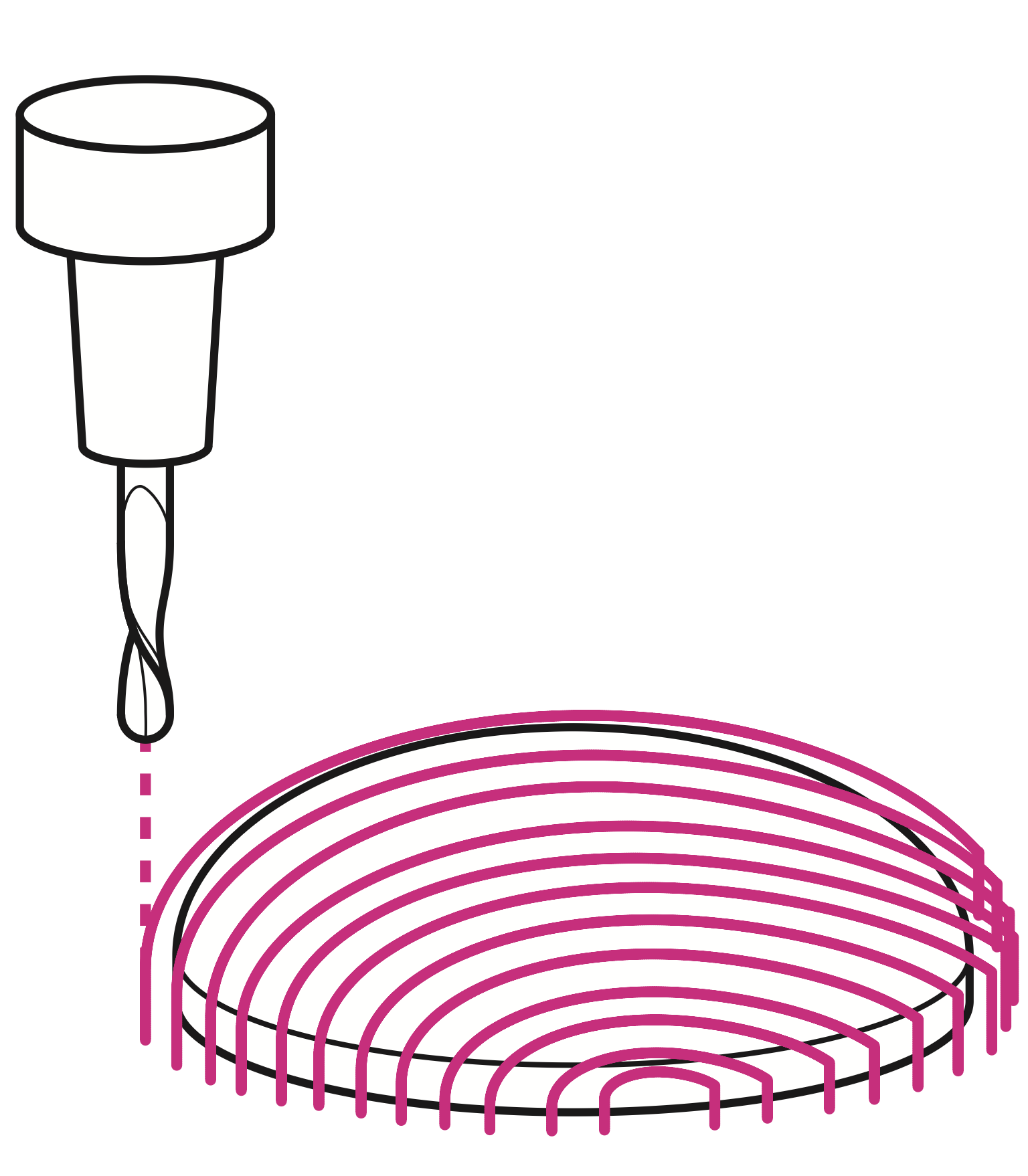
Removes a small amount of material to create a smooth surface finish and achieve the final dimensions of the part. The tool path is designed to minimize tool marks and create a high-quality finish. Usually requires a slower feed rate and higher spindle speed than roughing, and may use a different tool with a smaller diameter and rounder cutting edges.
¶ Contour
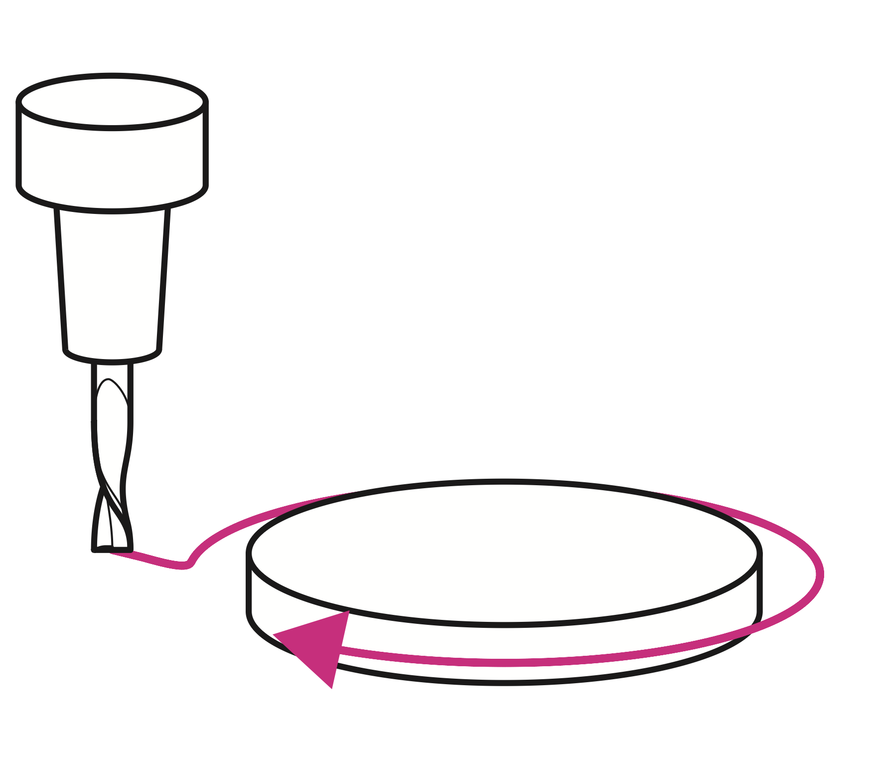
Removes material along a defined path to create a specific shape or profile on the part. Usually the final process used to machine the outside profile of the part to detatch it from the stock.
¶ Tools
A wide range of tool types and configurations are available for CNC milling machines. Discussing every type, variation and use is beyond the scope of this course. This chapter introduces the most commonly used tools for prototype and short run production machining. Any tool supply catalog will list many others.
- End mills (Flat, Ball, Bull and Chamfer)
- Face mill
- Corner Rounding tools
- Slot Tools
- Spot-Center Drill
- Twist Drill
- Tap
- Reamer
- Counterbore
¶ End Mills
Milling tools include flat, ball, bull nose and chamfer.
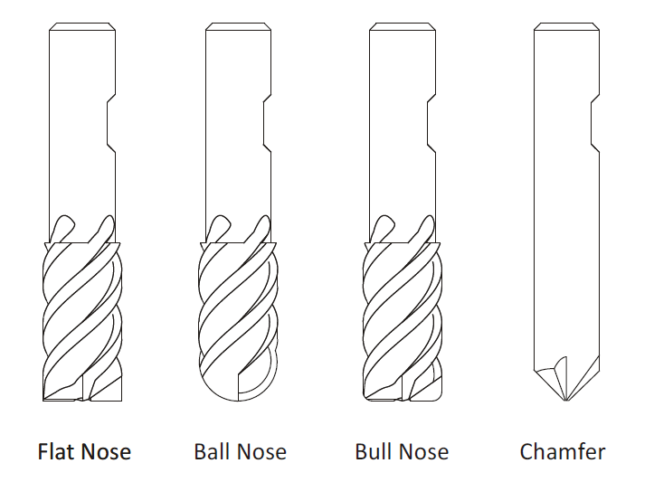
Mill Tool Nose Types
Flat nose mills are used for milling 2D contours and pockets. Ball nose mills are used for 3D milling. Bull nose end mills have a radius corner. They are used to create a fillet on the bottom of a wall. Because they are sturdier than an end mill they are also sometimes used for roughing operations. Chamfer mills have an angled nose used to create a chamfer or to de-burr parts.
¶ Number of Flutes
Milling tools usually have either two or four cutting flutes. Two flute cutters provide more chip clearance when milling in close areas. Four flute mills are more rigid, can be fed faster, and are preferred when greater chip clearance is not required, such as when milling an outside contour.
¶ Center-Cutting End Mills
Milling tools are either center cutting or non-center cutting. Center cutting mills can plunge straight down into material, while non-center cutting tools cannot. Figure 2 below shows the cutting end view of a center cutting and non-center cutting end mill. Notice that the cutting edges of the center cutting end mill continues to the center of the tool. The center of the other has a small hole at the center. Non-center cutting end mills require a pilot hole, ramping or helical motion to plunge into material.
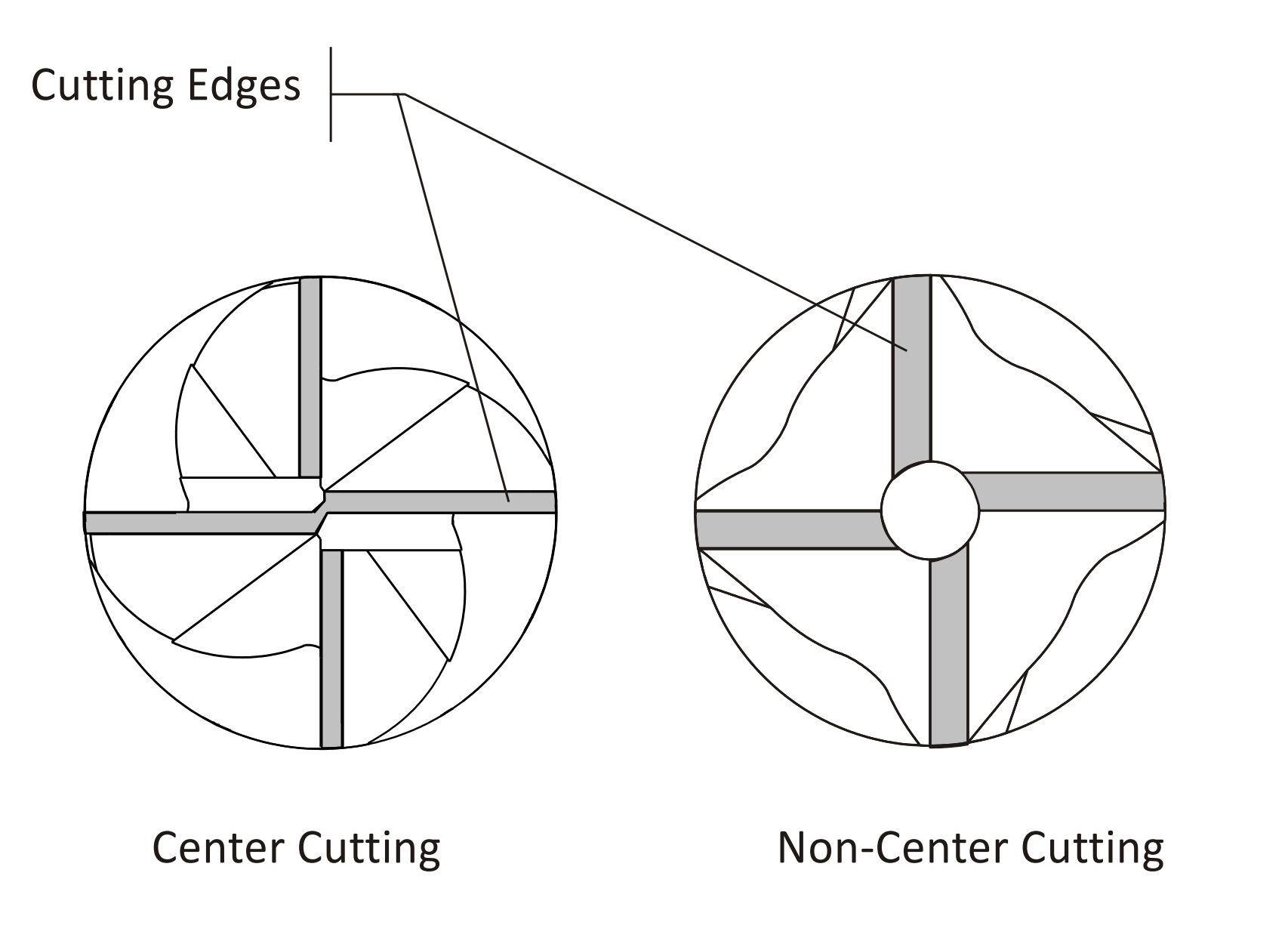
End View of Center and Non-Center Cutting End Mill
¶ Face Mill
A face mill has cutting inserts that are replaced when worn. They are rigid, may have up to eight or more cutting edges, and can remove material quickly. They are often used for the first machining operation to quickly create a flat finished face on the part.
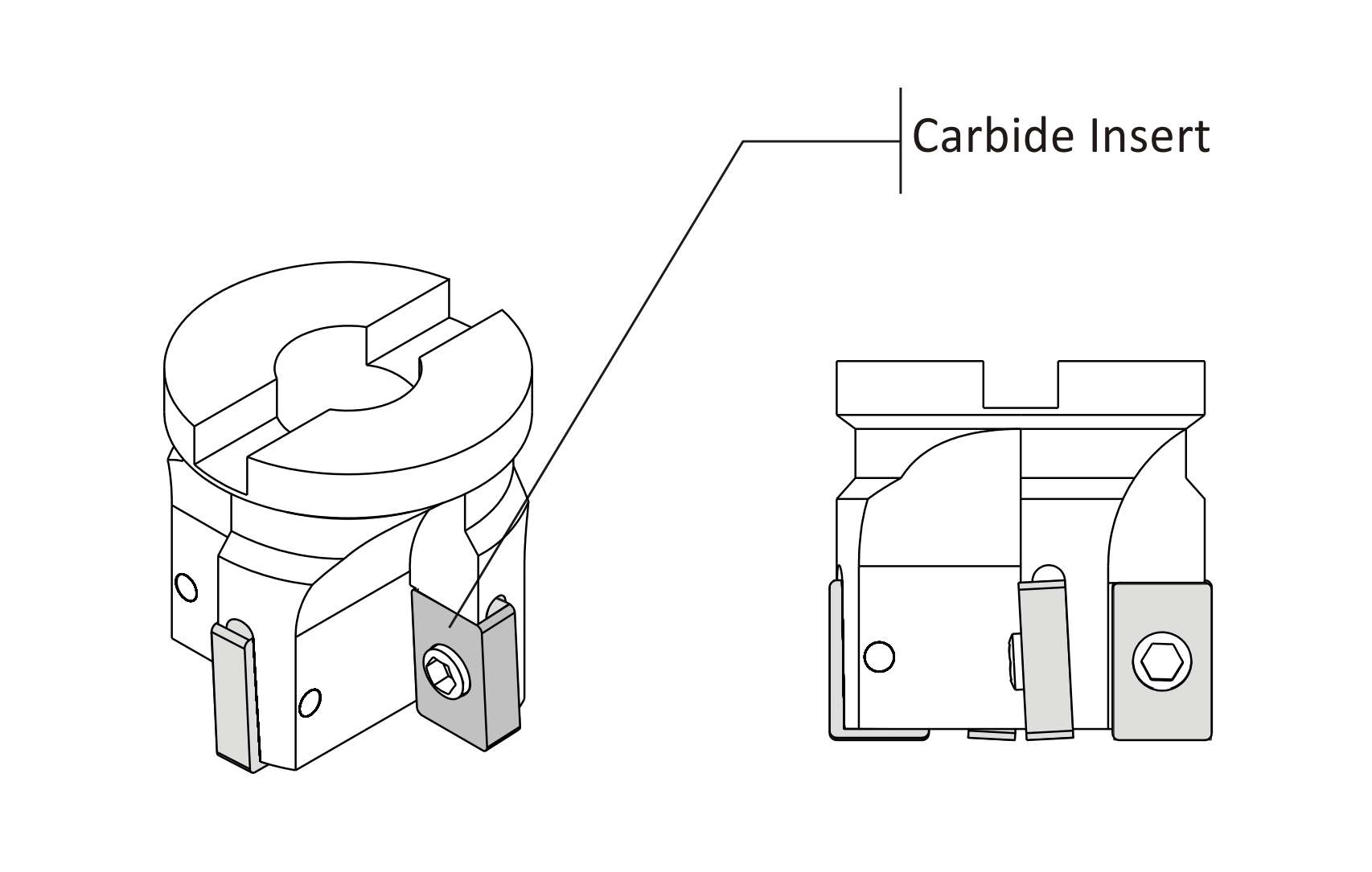
Face Mill
¶ Corner Radius Tool
Corner radius (also called Corner Round) tools are used to place a fillet on the outside corner of a part.
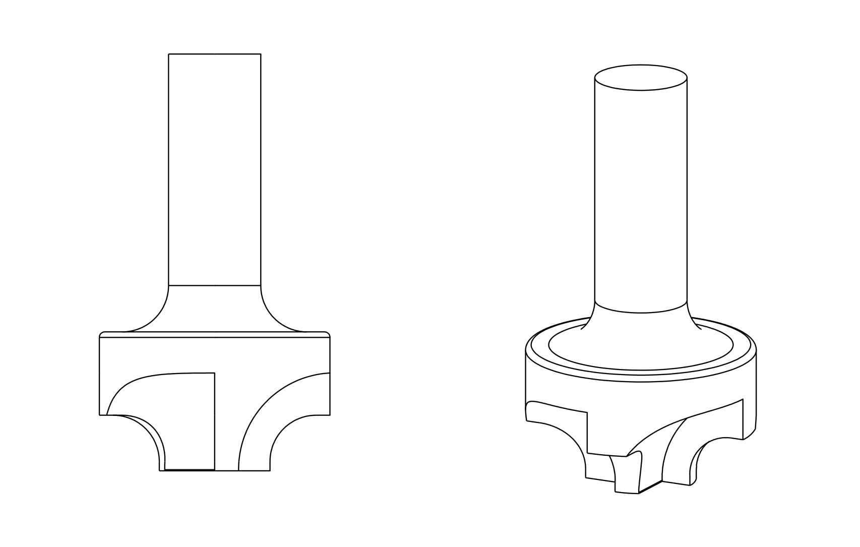
Corner Round Tool
¶ Slot Mill/Slotting Saw
Slot mills include side milling cutters, slitting saws, and Woodruff keyset cutters. Slitting saws and side milling cutters are installed on a special arbor. Woodruff cutters are single piece tools used for creating slots and undercuts that can be held in a standard tool holder.
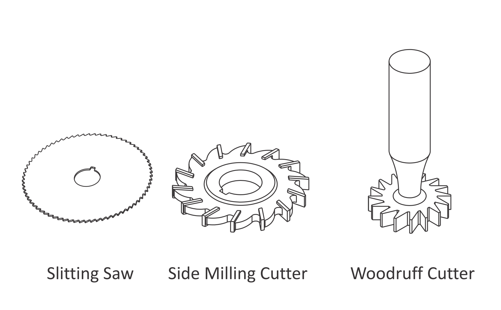
Slot Tools
¶ Hole-Making Tools
¶ Center-Spot Drills
Center (spotting) drills are short and very rigid drills used to create a conic on the face of the part. Because they come to a sharp point and resist bending, they locate the hole precisely. The conic helps prevent the subsequent drill from wobbling and ensure the drill is located precisely and drills straight down. Countersink drills are used to create the conical face for a machine screw. Combined spotting-countersinks are used to create a screw clearance hole and countersink in one operation. There are many different sizes and tip angles of center, countersink, and combined drills. Be sure the tip angle of the countersink matches the included angle of the machine screw, and that the drill diameter is greater than the screw head diameter.
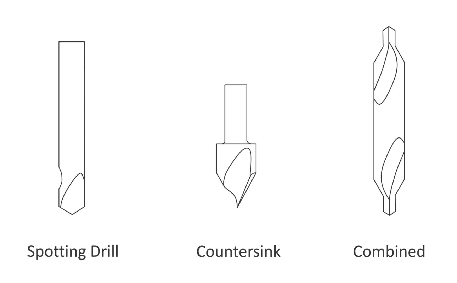
Countersink and Center Drill
¶ Twist Drill
Twist drills are available in many diameters and lengths. Usually made of high speed steel, carbide, or cobalt, they may also be coated with titanium nitride (TiN) for longer life. The tip angle of most twist drills is 118 degrees.
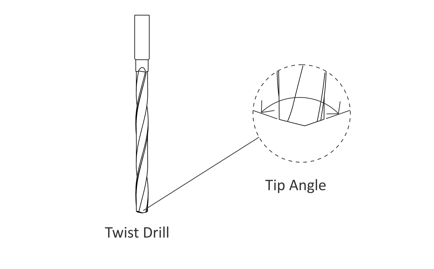
Twist Drill
¶ Taps
Cutting taps form threads by shearing material away. Form taps (roll taps) form the thread by forming the metal to shape. Form taps produce no chips and are used for soft materials including aluminum, copper, brass and plastics.
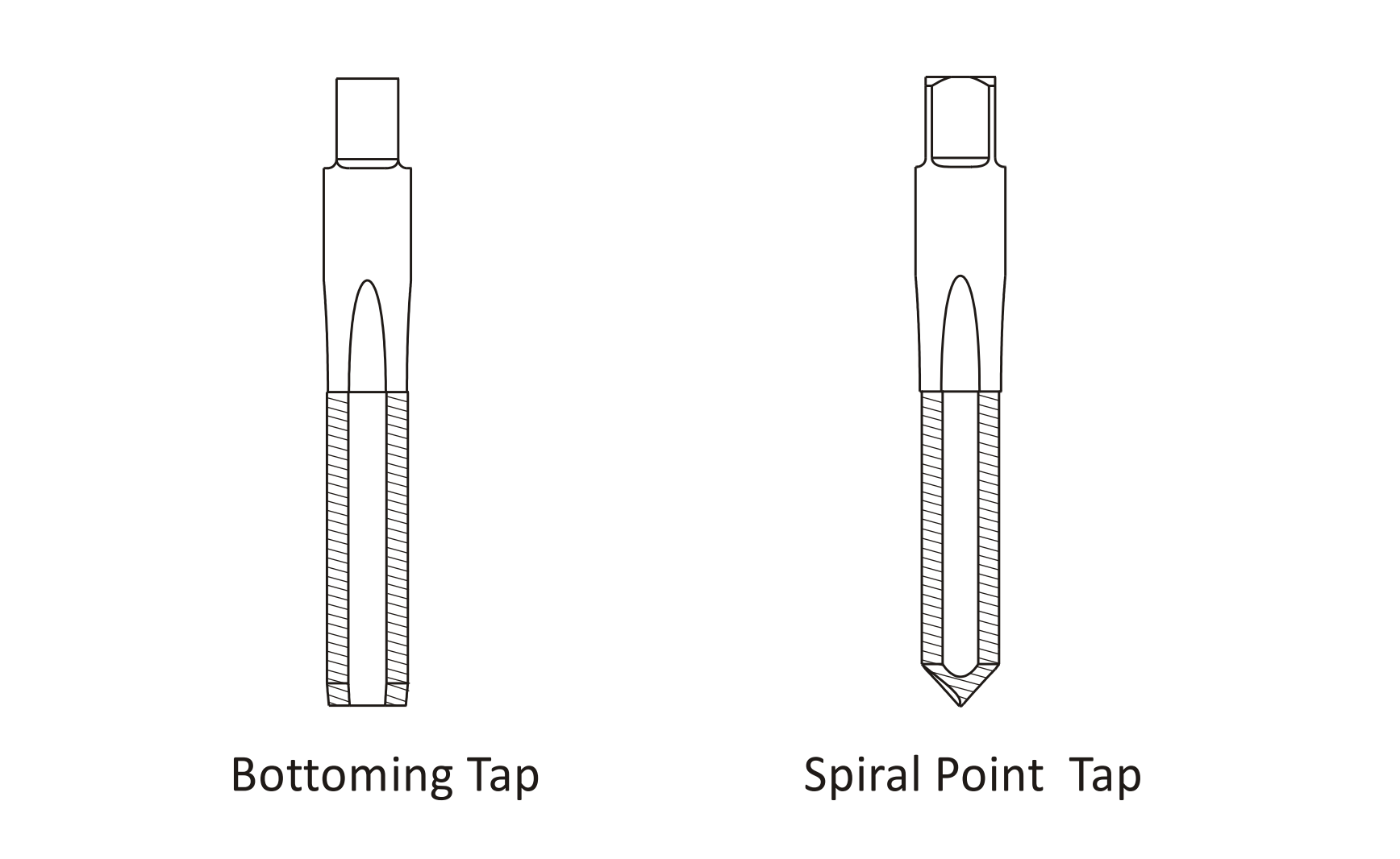
Taps
Bottoming taps are used to tap blind holes. Spiral point taps push the chip ahead and out the bottom of a through hole. Taps require a hole drilled to the correct size to ensure the thread is formed properly. For example, a ¼-20 cutting tap requires drilling a .201 (#7) hole. Refer to the drill chart in Appendix A to find the correct drill size for a specified thread size and fit. Most CNC Machines support rigid tapping, which means the tap can be held in a rigid holder. The tap is advanced at a feed rate that matches the thread lead into the hole. The spindle then stops, reverses, and backs out of the hole. Machines without rigid tapping require special tapping attachments. Always refer to the manufacturers’ instructions as the speed, feed, and other machining parameters for tapping attachments may be different that those for rigid tapping.
¶ Reamer
Use reamers to create holes of precise shape and excellent surface finish. Reamed holes are usually accurate within .0002 inches diameter. For example, a reamer is used for holes used for ground pins and bushings. Reamers require a specific size hole be drilled before use. Cutting speeds and feeds are also important. Remove too little or too much material and the hole will not be the correct size.
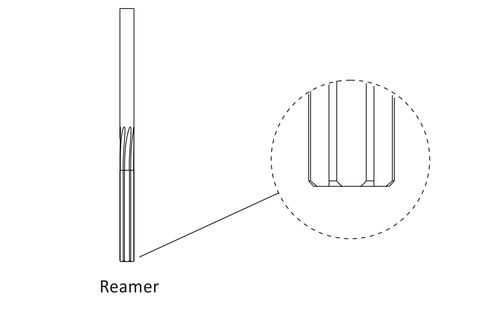
Reamer
¶ Counterbore
A counterbore looks similar to a end mill with a pilot in the center. It is used to spot face holes, and the pilot ensures the spot face is centered on the hole. Counterboring is not necessary when using a CNC machine. Rather, create a spot face using a pocket or circle mill tool path. This saves having to buy and stock counterbore tools and pilots, and the time required to load and set up the counterbore.
¶ Cutting Parameters
In milling, the speed and motion of the cutting tool is specified through several parameters. These parameters are selected for each operation based upon the workpiece material, tool material, tool size, and more. The following are the key cutting parameters used in milling:
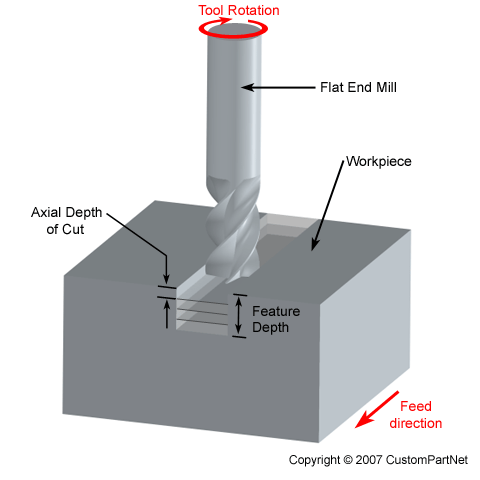
Axial Depth of Cut (image credit: https://www.custompartnet.com/wu/milling)
- Cutting feed - The distance that the cutting tool or workpiece advances during one revolution of the spindle and tool, measured in inches per revolution (IPR). In some operations the tool feeds into the workpiece and in others the workpiece feeds into the tool. For a multi-point tool, the cutting feed is also equal to the feed per tooth, measured in inches per tooth (IPT), multiplied by the number of teeth on the cutting tool.
- Cutting speed - The speed of the workpiece surface relative to the edge of the cutting tool during a cut, measured in surface feet per minute (SFM).
- Spindle speed - The rotational speed of the spindle and tool in revolutions per minute (RPM). The spindle speed is equal to the cutting speed divided by the circumference of the tool.
- Feed rate - The speed of the cutting tool's movement relative to the workpiece as the tool makes a cut. The feed rate is measured in inches per minute (IPM) and is the product of the cutting feed (IPR) and the spindle speed (RPM).
- Axial depth of cut - The depth of the tool along its axis in the workpiece as it makes a cut. A large axial depth of cut will require a low feed rate, or else it will result in a high load on the tool and reduce the tool life. Therefore, a feature is typically machined in several passes as the tool moves to the specified axial depth of cut for each pass.
There are many other cutting parameters that can be specified for a milling operation. For detailed guides:
¶ CAM
¶ Machine Operation
¶ Safety
¶ CNC Machining Safety Practices
Use these extra precautions when running a CNC program for the first time:
- Use machine Rapid and Feed override controls to slow the machine down.
- A major cause of crashes is setting the tool or fixture offset incorrectly. Pay particular attention to moves at the start of program and immediately after a tool change as the tool moves towards the part. Use single-block mode to advance through the program one line at a time until the tool is at cutting depth.
- Remain at the machine with a hand on or near the emergency stop button.
- Stop machine motion at the first sign of trouble.
¶ Guides
This section contains guides on how to perform specific tasks related to CNC machining.