¶ Overview
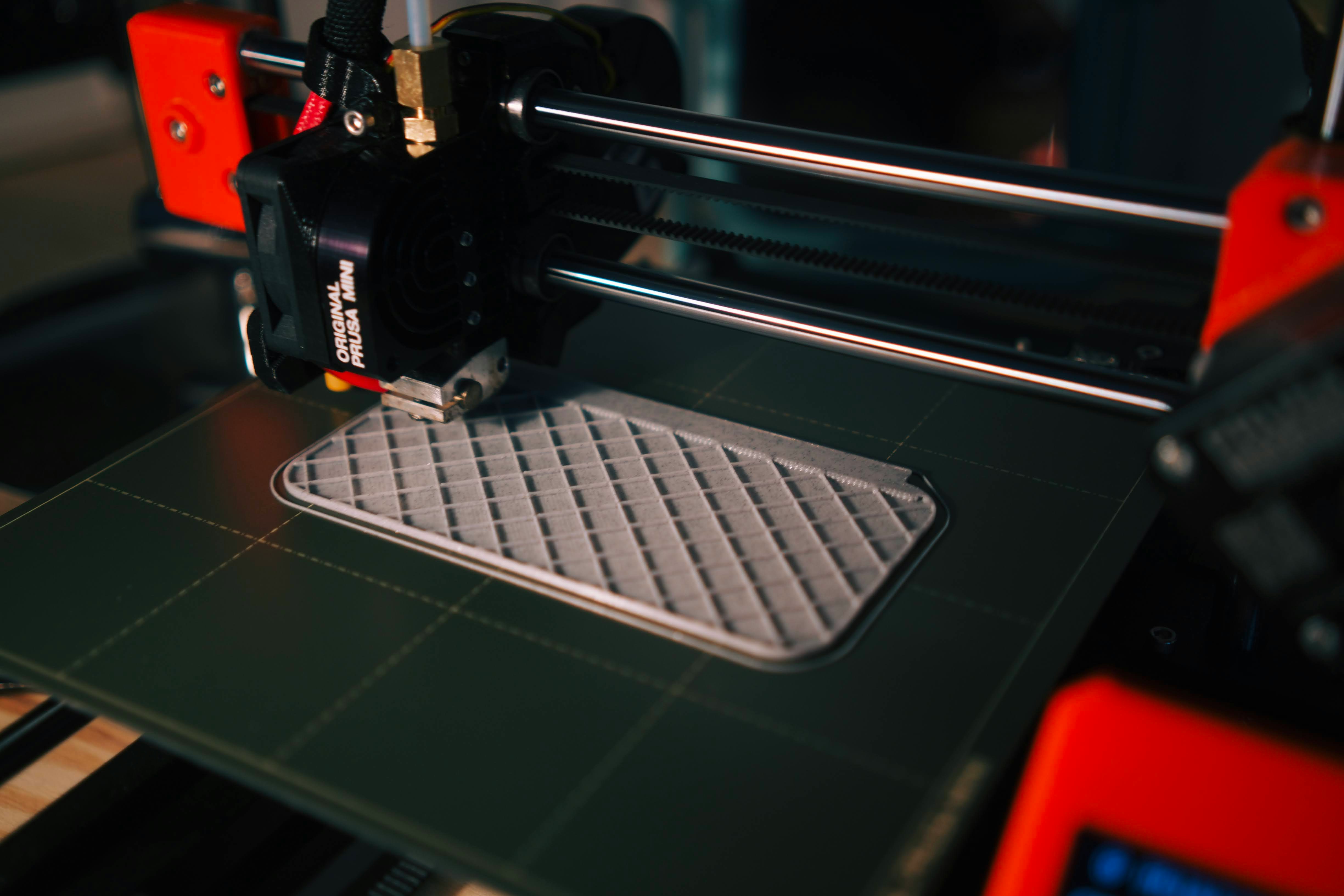
3D Prinitng (image credit: Kadir Celep)
The creation of a 3D printed object is achieved using additive processes. In an additive process an object is created by laying down successive layers of material until the object is created. Each of these layers can be seen as a thinly sliced horizontal cross-section of the eventual object.
¶ Technologies
Part of the information in this section is adapted from Protonlabs Network.
In 2015, the ISO/ASTM 52900 was created to standardize how 3D printers and 3D printing technology are classified. A total of seven process categories were established.
- Material extrusion: molten thermoplastic (filament) deposited through a heated nozzle
- Vat polymerization: liquid photopolymer (resin) cured by light
- Powder bed fusion (PBF): powder particles fused by a high-energy source
- Material jetting: droplets of liquid photosensitive fusing agent deposited on a powder bed and cured by light
- Binder jetting: droplets of liquid binding agent deposited on a bed of granulated materials, which are later sintered together
- Direct energy deposition: molten metal simultaneously deposited and fused
- Sheet lamination: individual sheets of material cut to shape and laminated together.
Currently all 3D printers at Raccoon are FDM 3D printers.
¶ Material Extrusion
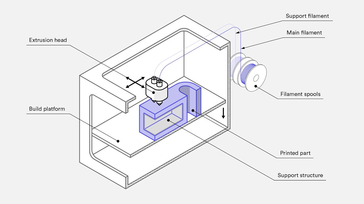
Schematic of a typical FDM printer (image credit: Protolabs Network)
Material extrusion is the most common 3D printing technology. It works by extruding a semi-liquid material through a nozzle to create a 3D object. Among the different types of material extrusion, Fused Deposition Modeling (FDM) is the most popular. In FDM, a thermoplastic filament is heated and extruded through a nozzle, where it is deposited layer by layer to create the final object.
¶ Vat Photopolymerization
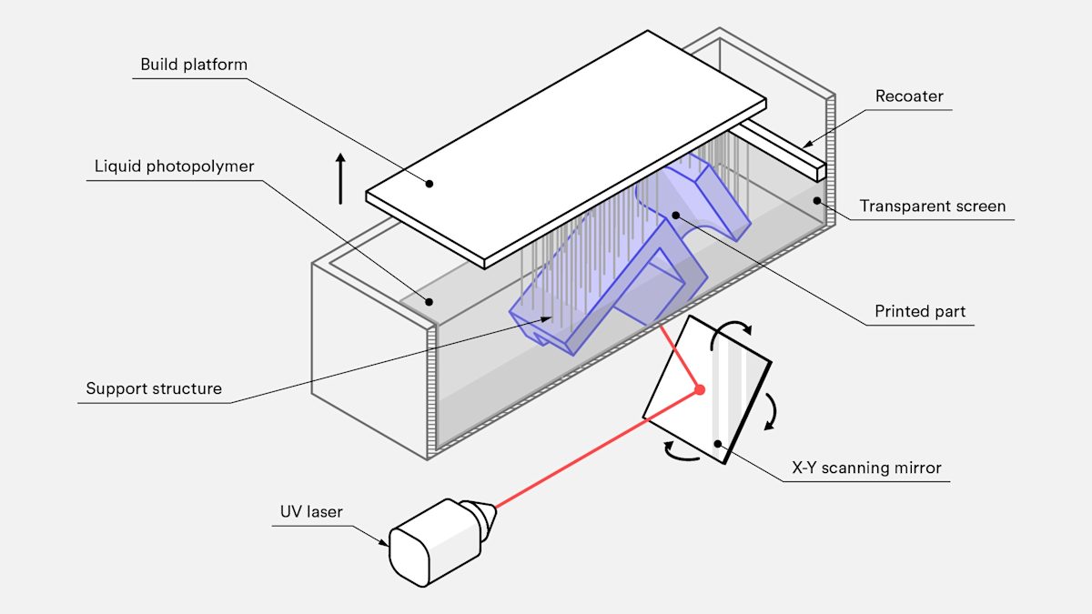
Schematic of a typical SLA printer (image credit: Protolabs Network)
Vat photopolymerization produces parts by selectively curing liquid photopolymer resins with a UV light source. A build platform is submerged in a tank that is filled with resin. The light is selectively directed across the resin surface with mirrors.
Once a layer is cured, the platform is raised or lowered in a small increment to allow new liquid to flow. The next layer is then cured and adjoins the previously cured one. After the final layer is cured, the print is removed from the resin. At this stage, it is fully formed though can be strengthened with further curing in a UV oven.
Vat photopolymerization has a few distinct printing technologies.
- SLA uses a single-point laser to trace a thin line along the surface of the resin, filling in the shape of the cross-sectional layer to be cured. It is highly accurate but can be time-consuming.
- DLP uses a digital light projector to flash a single image of an entire layer all at once. This makes it faster than SLA. However, because the projector is a digital screen, the image of each layer is composed of square pixels, resulting in a slightly lower resolution.
- CLIP is the same as DLP except that the build platform moves in a continuous motion. This allows for even faster build times and smoother contours along the z-axis.
¶ Powder Bed Fusion
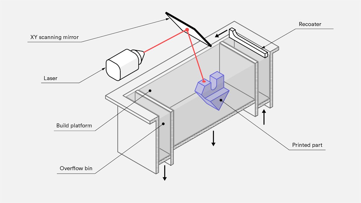
Schematic of a typical SLS printer (image credit: Protolabs Network)
Powder bed fusion printers produce parts by selectively melting or sintering powdered particles together to form a whole object. The powder material is heated to just below its melting point and spread over the build platform in a very fine layer. A laser or electron beam is then directed across the powder’s surface, fusing particles together to form a single cross-section of the print.
After each layer, the build platform is lowered and the process repeats. Each new layer is fused to the previous until all the layers have been fused into one object.
As layers are built on top of one another, the unfused particles act as a support structure for the print, thereby eliminating the need for most separate support structures. Once the print is complete, the excess supporting powder is removed and recycled.
¶ Materials
¶ Printing Filament
The most common material used in FDM 3D printing is thermoplastic filament. The two most common types of filament are ABS (Acrylonitrile Butadiene Styrene) and PLA (Polylactic Acid). Both materials have their own unique properties and are suitable for different applications.
¶ ABS
- Strength: ABS is stronger and more flexible than PLA, making it a good choice for functional parts.
- Temperature resistance: ABS has a higher glass transition temperature than PLA, making it more suitable for parts that will be exposed to high temperatures.
- Toxicity: ABS emits toxic fumes when melted, so it should only be used in a well-ventilated area.
- Warping: ABS has a tendency to warp as it cools, so it requires a heated build plate to prevent warping.
¶ PLA
- Non-toxic: PLA is made from renewable resources and is biodegradable, making it an environmentally friendly choice.
- Ease of use: PLA is easier to print with than ABS and does not require a heated build plate.
- Brittleness: PLA is more brittle than ABS, so it is not suitable for parts that will be subjected to high stress or impact.
- Temperature resistance: PLA has a lower glass transition temperature than ABS, so it is not suitable for parts that will be exposed to high temperatures.
¶ Printing Temperatures
| Material | Nozzle Temperature | Bed Temperature |
|---|---|---|
| PLA | 190-210°C | 50-60°C, or none |
| ABS | 230-240°C | 90-110°C |
¶ Slicing
¶ General Operation
Sclicing is the process of converting a 3D model into a set of instructions for a 3D printer. These instructions are usually in the form of G-code, which is a language that many CNC machines understand. The slicer software takes into account the printer's capabilities and the desired print quality to generate the G-code.
-
Set up the printer in the slicer
The printer's specifications need to be entered into the slicer software so that it can generate the correct G-code. This usually involves selecting the printer model and entering the build volume and other parameters. -
Import the 3D model
Import the 3D model, usually in the form of anSTLfile, into the slicer software. The software will then allow you to arrange, position, and scale the model as needed. -
Configure print settings
The slicer software will have a wide range of settings that can be adjusted to control the print quality and speed. These settings include layer height, infill density, print speed, and many others. -
Common print settings
- Layer height: This setting determines the thickness of each layer of the print. A smaller layer height will result in a smoother surface finish, but will also take longer to print.
- Infill density: This setting determines how much of the interior of the print is filled with material. A higher infill density will result in a stronger print, but will also take longer to print.
- Print speed: This setting determines how fast the print head moves while printing. A higher print speed will result in a faster print, but may also reduce print quality.
- Support material: This setting determines whether the slicer will generate support structures for overhanging parts of the print. Support material can be difficult to remove and can leave a rough surface finish, so it is best to use as little as possible.
- Build plate adhesion: This setting determines how the print will stick to the build plate. A good build plate adhesion is essential for a successful print.
- Temperature: This setting determines the temperature of the print head and the build plate. Higher temperatures can improve layer adhesion and print quality, but may also increase the risk of warping and stringing.
- Advanced print settings
- Wall, top, and bottom thickness: These settings determine the thickness of the walls, top, and bottom layers of the print. Properly tuned wall thickness can improve print strength and surface finish.
- Speed for different print moves: This setting determines how fast the print head moves during different parts of the print. Different speeds can be used for travel moves, outer wall moves, inner wall moves, and infill moves. Properly tuned speeds can improve print quality and reduce print time.
- Print cooling: This setting determines how the print head cooling fan is used. A well-tuned print cooling system can improve print quality.
- Retraction: This setting determines how the filament is retracted when the print head moves between different parts of the print. Proper retraction settings can reduce stringing and oozing.
-
Slice and verify
Once the print settings have been configured, the slicer software will generate the tool path and a preview of the print. The preview will show the layers of the print and any support structures that have been generated. This allows you to verify that the print will be successful before starting the print. -
Save the G-code
This step is also known as post-processing. The slicer will generate vendor-specific G-code that can be used to control the printer. Most G-code files will have a.gcodeextension, yet some printers may require a different file format.
For file naming conventions at Raccoon, we follow this format:
<MACHINE>_<FILENAME>_<WEIGHT>_<PRINT_TIME>.gcode. For instance, your file should be namedPRS_TEST1_100G_5H30M.gcode. This naming convention ensures clarity regarding the intended machine, print duration, and material usage, which is particularly useful when multiple printing tasks are ongoing simultaneously, preventing the accidental sending of large prints to the wrong machine."
- Print
The G-code file can be loaded onto the printer and the print can be started.
¶ Slicer Guides
¶ Machine Operation
¶ Modeling Guidelines
When designing parts for 3D printing, there are a few things to keep in mind to ensure a successful print. These guidelines will help you design parts that are easy to print and that will have good mechanical performance.
¶ Orientation
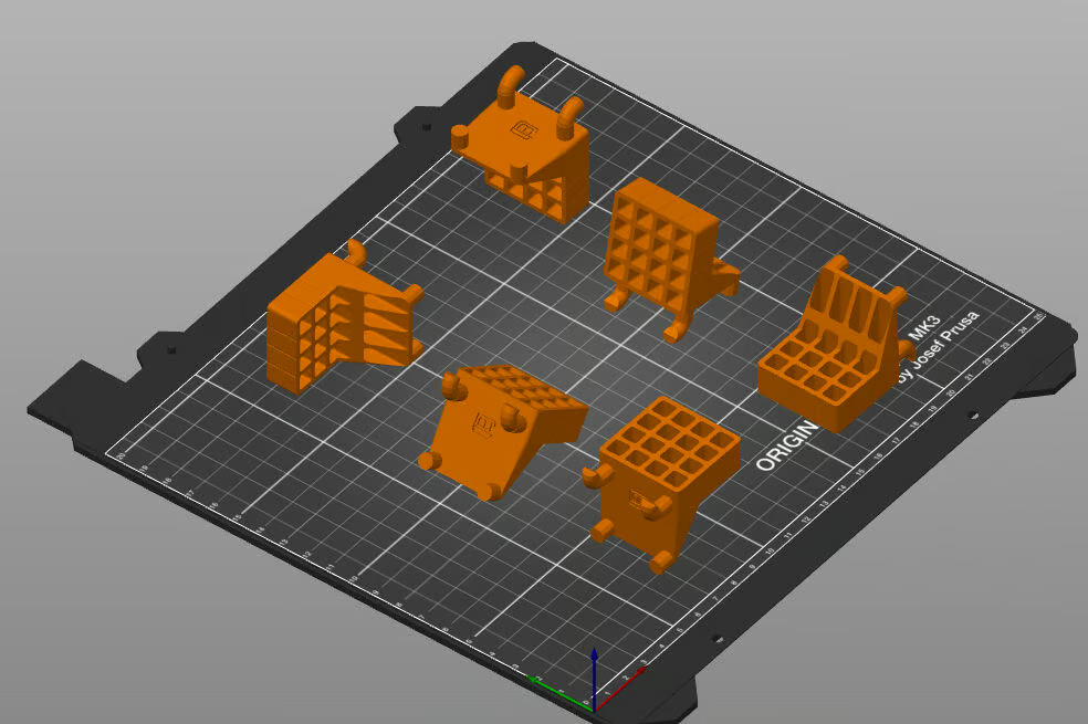
There can be many ways to orient a part (image credit: Mark VanHorne via All3DP)
Orientation is one of the most important factors to consider when designing and printing a part. The orientation of the part can affect the print quality, strength, and appearance of the part. Here are some factors to consider when choosing the orientation of your part:
-
Bed Adhesion : Identify the faces of the part that will provide good adhesion to the build plate. Most slicers provide features like rafrs and brims to help with bed adhesion.
-
Stability If the part is tall and thin, it may be more prone to tipping over during printing. If necessary, add features to the part that will increase its stability during printing.
-
Mechanical Peroformance If your part will experience mechanical loads, consider the orientation that will provide the best mechanical performance. For example, if the part will be subjected to shear forces, orient it so that the layers are perpendicular to the direction of the force.
-
Supports Minimize the need for support material. Supports can be difficult to remove and can leave a rough surface finish. Also, supports can be time-consuming to print and can increase the risk of print failure.
-
Dimensional accuracy Features of the part that must meet close dimensional tolerances may print better in some orientations than others. For example, cylindrical features print more accurately in the vertical direction than horizontally.
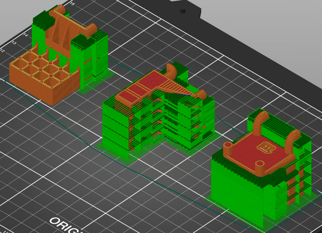
Three options, side by side (image credit: Mark VanHorne via All3DP)
¶ Feature Design
When designing parts for 3D printing, there are a few features that work well for 3D printed parts. These features can help improve the strength and printability of the part.
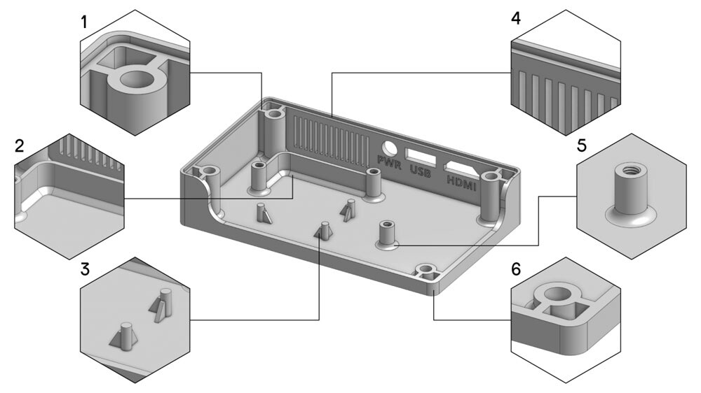
Useful features that work well for 3D printed parts (image credit: UltiMaker)
- Rib A rib is a special type of extruded feature that adds material of a specified thickness in a specified direction between the contour and an existing part. Ribs are fundamental features for enhancing the structural integrity of your 3D printed parts. Connecting the part to a wall strengthens the construction. It also supports the part from the bottom surface.
- Chamfer A chamfer is a beveled edge between two (near) perpendicular surfaces in the model. Using chamfers (often 45°) as a transition instead of sharp corners reduces stress and increases the strength of the connection.
- Gusset A gusset is a small triangular extra surface between extruded features and the bottom surface (or wall, when used for horizontal features). Gussets help to support features with more surface contact like a rib. However, they do not connect to another feature or wall, but it tapers off as the Z height increases.
- Wall thickness Generally, designs with a uniform and consistent wall thickness decrease the chance of warping or shrinkage. A consistent wall thickness will improve the overall stability of the printed part, and it avoids weak points in the design and extrusion changes.
- Fillet A fillet is a rounded corner between two surfaces. Similar to chamfers, fillets reduce stress in areas where two surfaces meet and strengthen the connection. Additionally, the smooth transition will often help to improve the visual quality of the print.
- Rounded corners Using rounded corners instead of sharp (90°) transitions help distribute the stress in the material more evenly throughout the model. This enhances the overall print quality and reduces the risk of weak points or fractures. Sharp corners can cause sudden changes in speed, acceleration, and the extrusion rate, which leads to visual quality issues such as ringing / ghosting.
¶ Interfacing
When designing parts that will interface with other parts, there are a few things to keep in mind to ensure a good fit and function.
¶ Tolerances
3D print parts tend to shrink slightly when they cool down. Also, the imperfection of the printer can cause the part to be slightly larger or smaller than the intended size. To ensure a good fit between parts, design the parts with a small amount of clearance between them. The amount of clearance will depend on the printer and the material being used, but a good rule of thumb is to use a clearance of 0.2mm to 0.5mm.
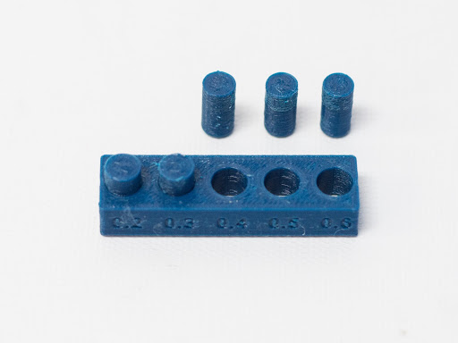
Tolerance for 3D printed parts (image credit: matterhackers.com)
¶ Post-Processing
Some features of a 3D printed part may require post-processing to achieve the desired fit and function. For example, holes may need to be reamed or drilled to the correct size.
¶ Intergrating pre-made parts
Instead of printing an entire assembly, consider integrating pre-made parts into your design. This can save time, and in many case, greatly improve the performance of the final product.
Nut and bolt assemblies are a good example of this. Instead of printing a nut and bolt, you can use standard hardware that is readily available and inexpensive.
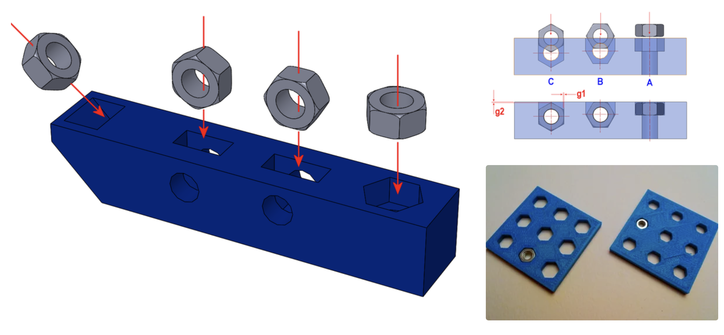
Embedding metal object inside 3D Printed parts (image credit: theGHIZmo)